Loading...

Last updated:

Overview

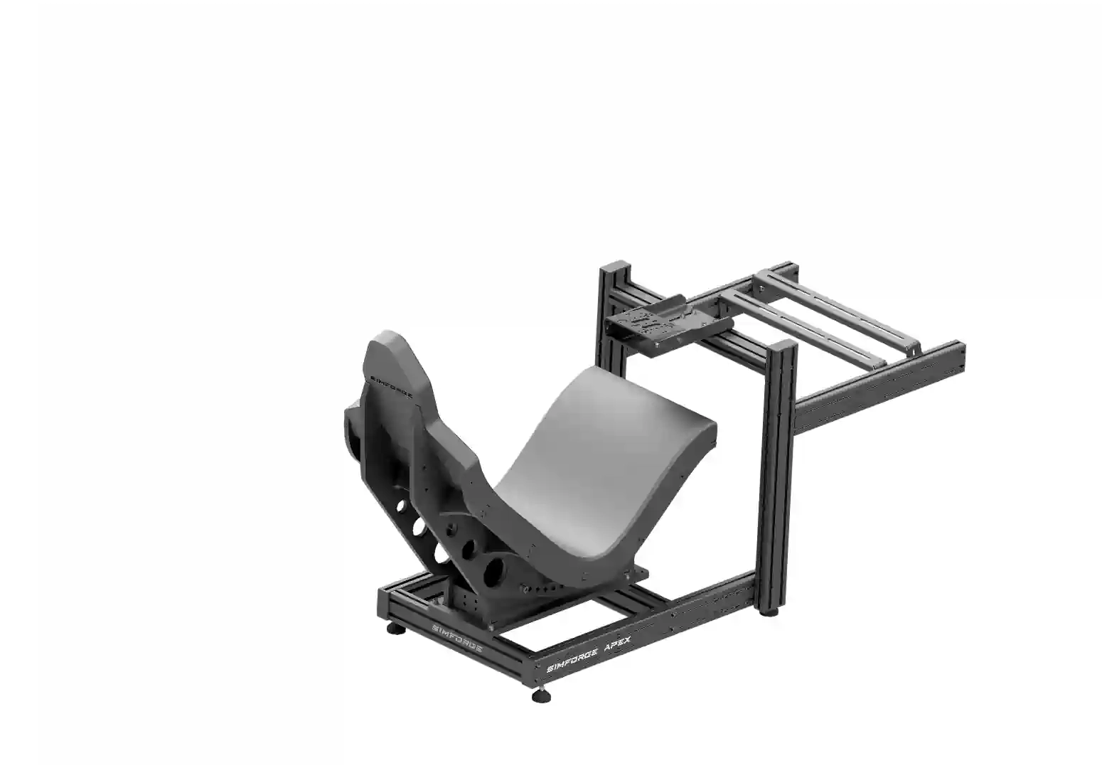
The Simforge Apex Sim Racing Cockpit , and Simforge Apex Sim Racing Seat is designed for professional sim racing drivers and enthusiasts who demand stability, adjustability, and ease of assembly. Built from heavy-duty aluminum profile and precision-cut steel components, this cockpit provides a rock-solid foundation for direct drive wheelbases, load cell pedals, and sim racing seats.

Its mostly bolt-on design makes assembly and adjustments fast and convenient, while integrated features like a universal wheelbase mount, angle-adjustable pedal deck, and optional monitor stands ensure full compatibility with leading brands such as Logitech, Thrustmaster, Moza, and Fanatec. Whether you race in iRacing, Assetto Corsa, F1 23, or Euro Truck Simulator, the Simforge Apex adapts to your setup.

This Simforge Apex Sim Racing Cockpit assembly manual serves as a detailed DIY setup guide for sim racing and flight simulation enthusiasts, fully compatible with Logitech, Thrustmaster, Moza, and Fanatec wheelbases.

NOTE

  • Please read this manual carefully before assembling your Simforge Apex Sim Racing Cockpit
  • The assembly can be done by one person. But it is recommended to be done by two people
  • Ensure you have all the (included) required tools (Allen keys, spanners, and screwdrivers) before beginning installation.
  • Assemble on a flat surface and tighten all bolts evenly to avoid misalignment.
  • Incorrect assembly may cause damage or affect the performance of your cockpit, pedals, and components.
  • Safety Warning: Do not overtighten bolts. Excessive force may cause thread damage or compromise structural integrity.

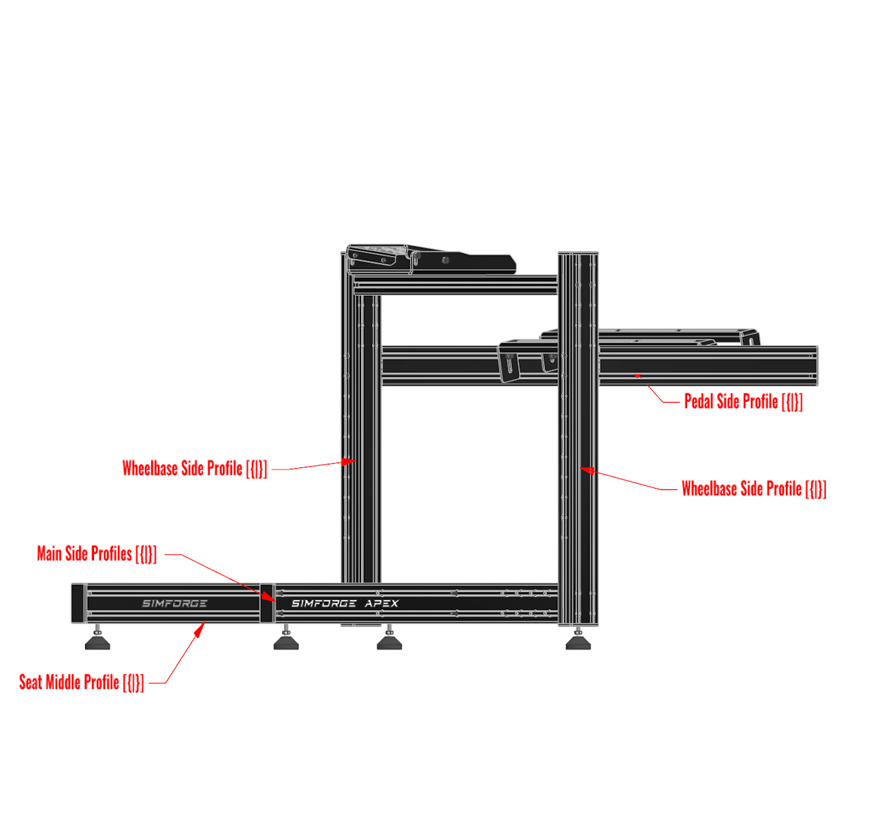
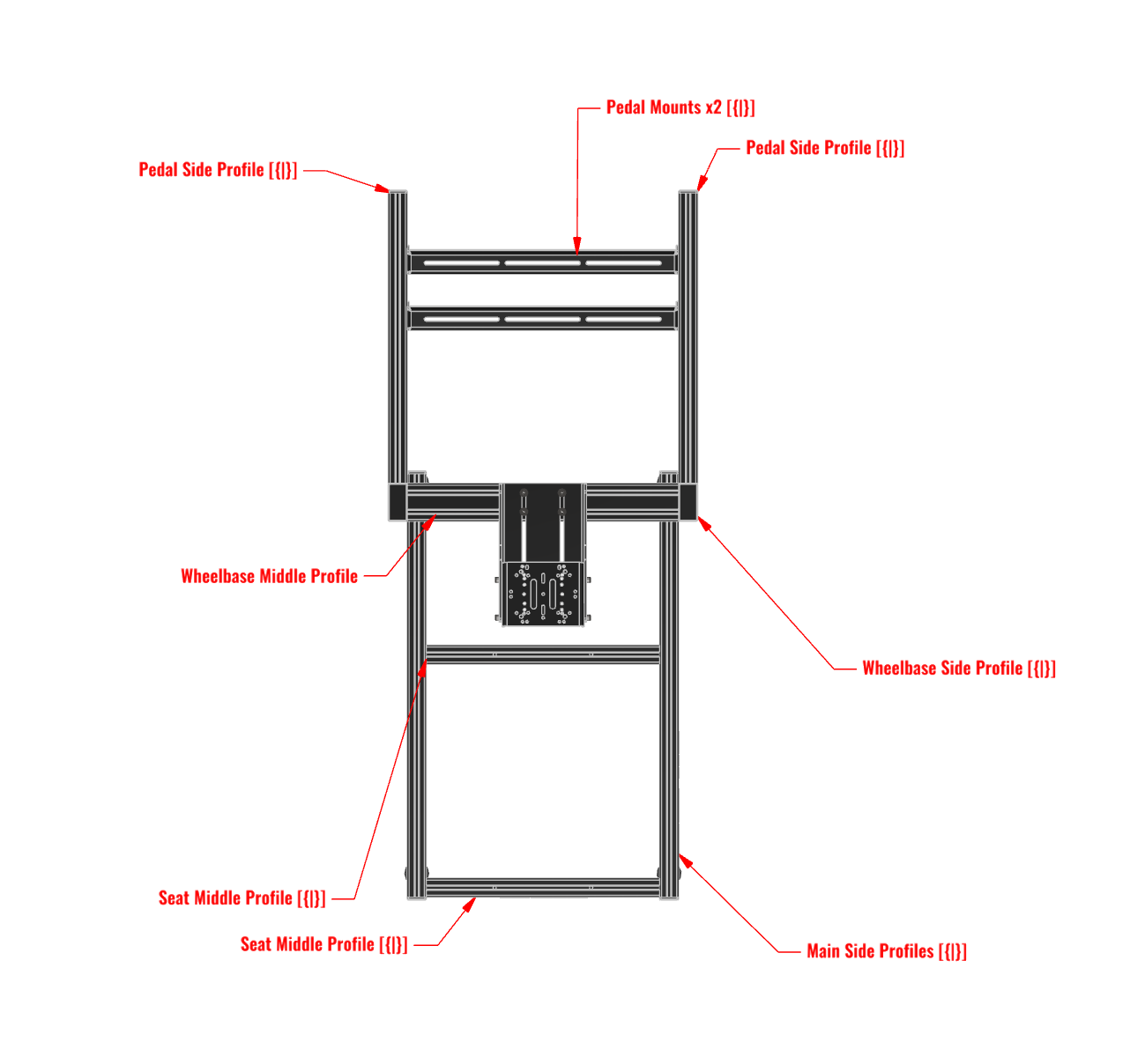
Assembly Diagram and Part Labels

  • πŸ‘‰ Profiles marked with [{|}] are symmetrical and can be used on the other side.
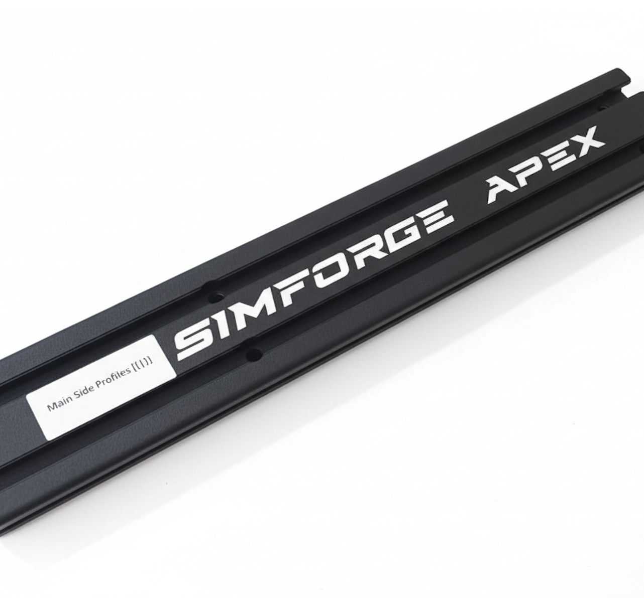
  • πŸ‘‰ All profiles are marked with temporary label stickers for quick and easy identification during assembly.
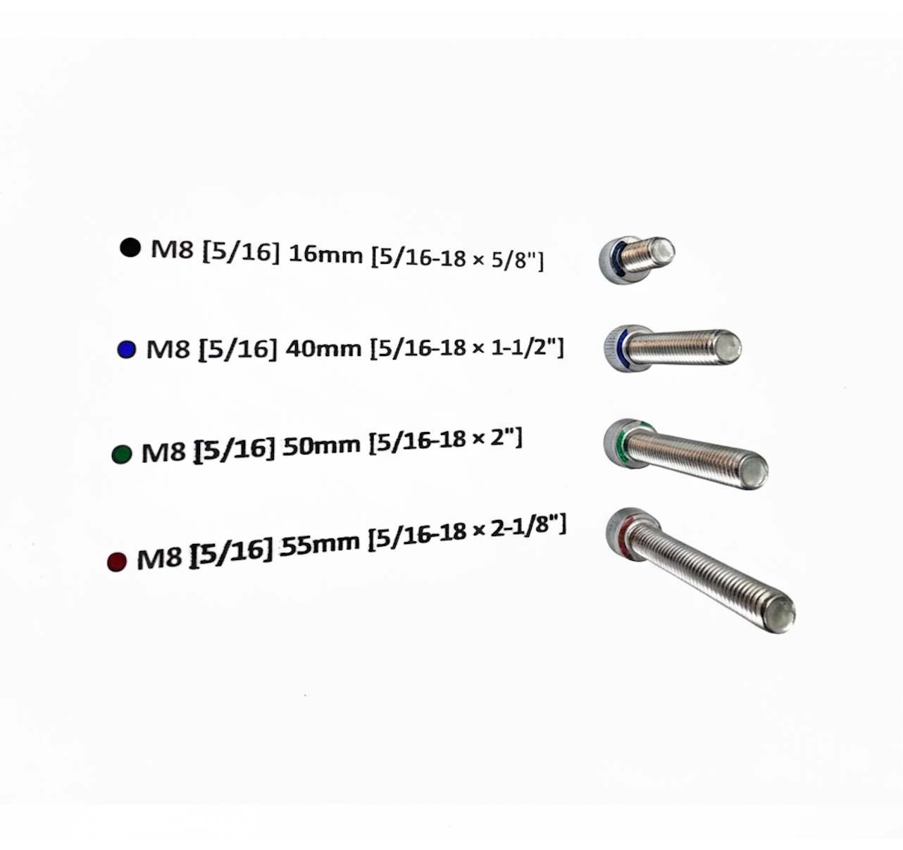
  • πŸ‘‰ All bolts for the Simforge Cockpit are color-coded for quick and easy identification during assembly.
Simforge Apex sim racing cockpit assembly diagram – isometric view showing profile labels Simforge Apex cockpit top view diagram with labeled aluminum profiles Simforge Apex cockpit parts labeling and bolt identification chart Simforge Apex bolt color code reference for M8 fasteners
Bolt colour code legend for Simforge Apex cockpit (M8 sizes)
Bolts Size Colour
M8 [5/16] 16mm [5/16-18 Γ— 5/8"] Black
M8 [5/16] 40mm [5/16-18 Γ— 1-1/2"] Blue
M8 [5/16] 50mm [5/16-18 Γ— 2"] Green
M8 [5/16] 55mm [5/16-18 Γ— 2-1/8"] Red
M8 [5/16] 90mm [5/16-18 Γ— 3-1/2"] White

4) Parts List

  • πŸ‘‰ * marked parts only included once if optional parts are purchased along with the cockpit.
Complete parts list for the Simforge Apex Cockpit
Simforge Apex Cockpit
Sr NoPartsQTY
1Seat Middle Profile [{|}]2
2Main Side Profile [{|}]2
3Wheelbase Side Profile [{|}]2
4Pedal Side Profile [{|}]2
5Wheelbase Middle Profile / Monitor Mount Middle Profile [{|}]1
6Plastic End Caps (Pre-installed)10
7Universal Wheelbase Mount1
8Universal Wheelbase Mount Base1
9Bolt – M8 Γ— 168
10M8 Washer8
11Bolt – M8 Γ— 5016
12Bolt – M8 Γ— 558
13Pedal Mounting Plates2
14Bolt – M8 Γ— 404
15M8 Profile Nuts4
16Leveling Feet4
Extra parts included for pedal and wheelbase mounting
Extra Parts Included for Pedal and Wheelbase Mounting
Sr NoPartsQTY
1Bolt – M6Γ—208
2M6 Hex Nut4
3M6 Washer4
Tools included with the Simforge Apex Cockpit
Simforge Apex Cockpit Tools
Sr NoPartsQTY
16mm Allen Key1
213mm Spanner/Wrench1
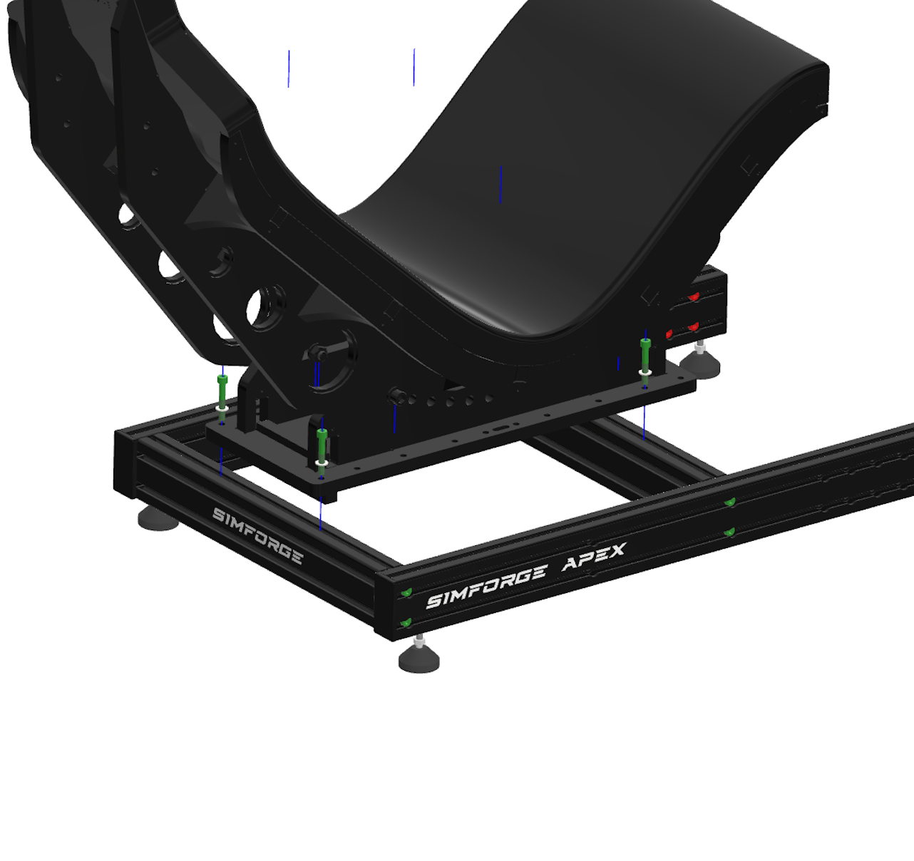
Parts included with the optional Simforge Apex Seat
Simforge Apex Seat (Optional)
Sr NoPartsQTY
1Seat1
2Bolt – M8 Γ— 504
3M8 Washer4
Tools included for installing the Simforge Apex Seat
Simforge Apex Seat Tools
Sr NoPartsQTY
119mm Spanner/Wrench1
28mm Allen Key1
36mm Allen Key*1
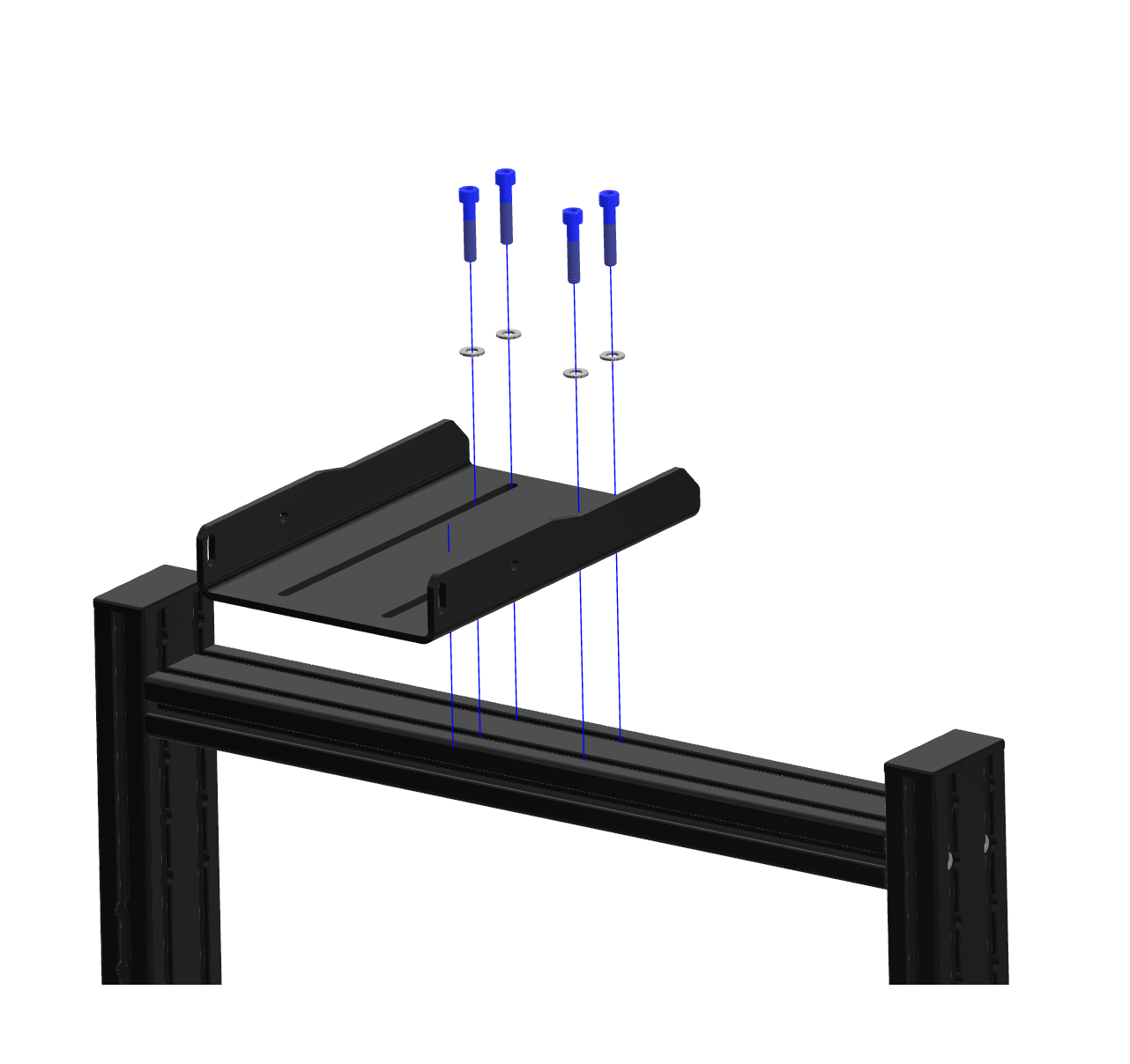
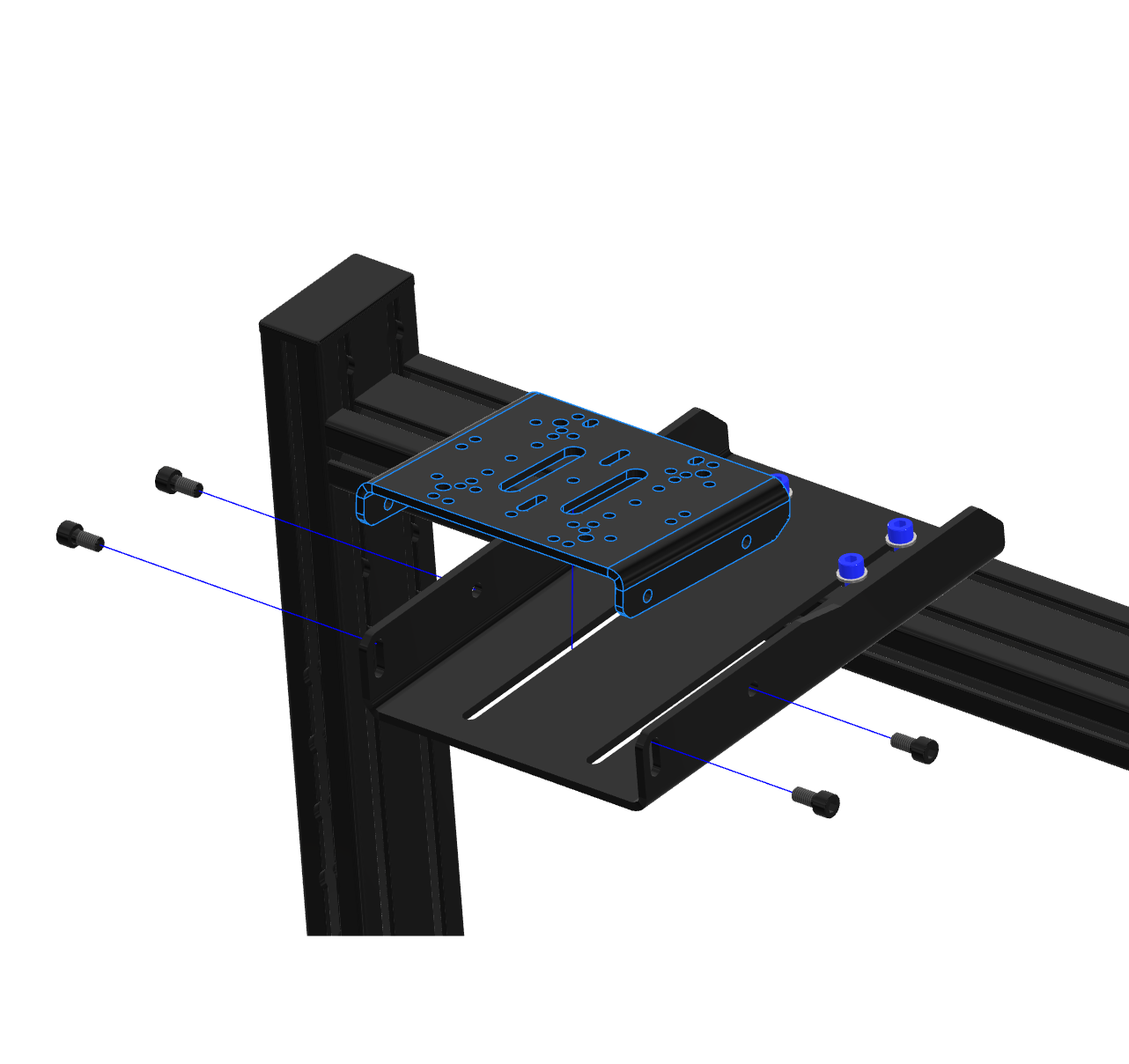
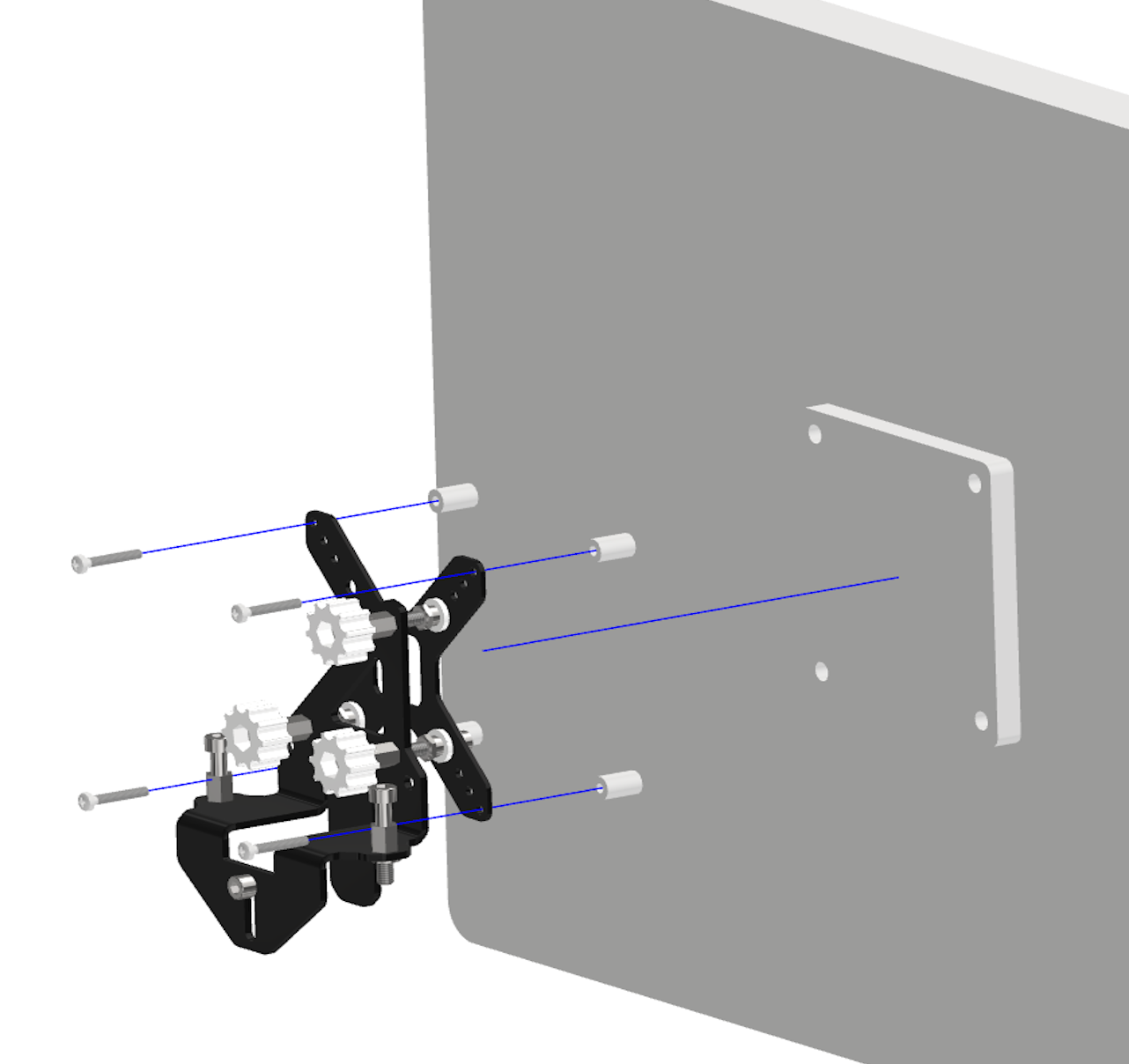
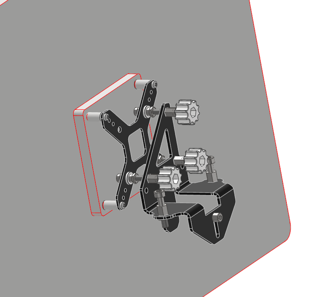
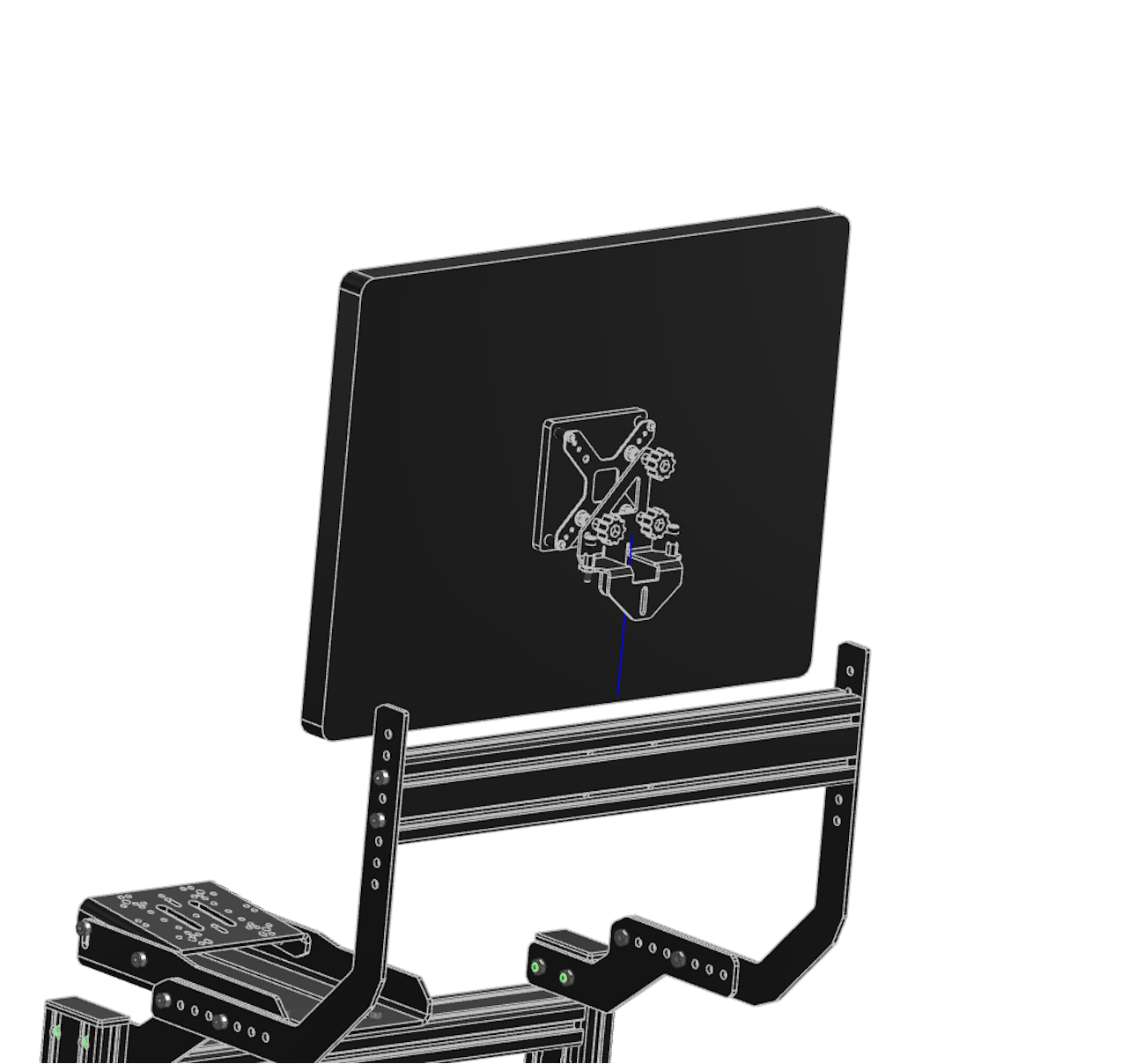
Parts included with the integrated single monitor mount (optional)
Integrated Single Monitor Mount (Optional)
Sr NoPartsQTY
1Back Mounting Plates2
2Wheelbase Middle Profile / Monitor Mount Middle Profile [{|}]1
3Bolt – M8 Γ— 168
4M8 Hex Nut4
5Bolt – M8 Γ— 404
6Front Mounting Plates2
7Adjustable Vesa Kit1

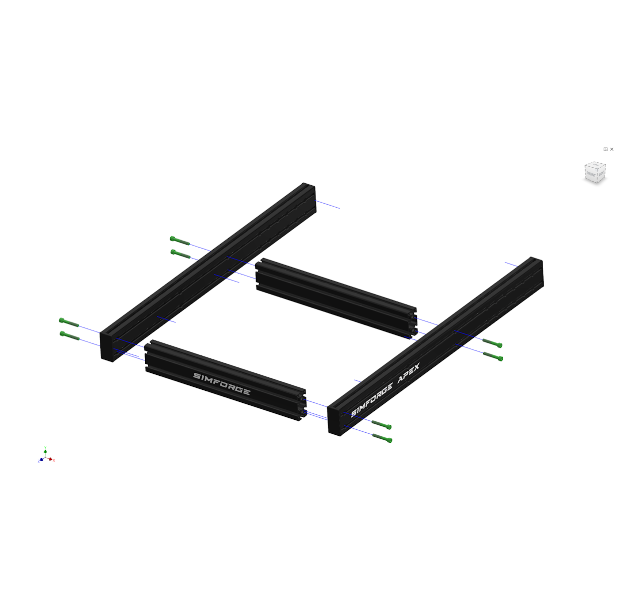
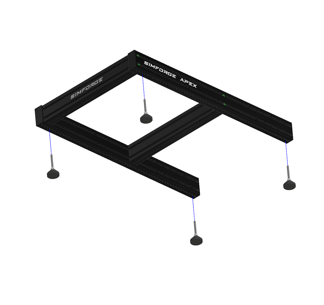
Cockpit Assembly Step 1

Parts used in Step 1 β€” base frame and leveling feet
Parts Used in this STEP
Sr No Parts QTY
1Main Side Profile [{|}]2
2Seat Middle Profile [{|}] 2
3Bolt – M8 Γ— 50 8
4Leveling Feet4
Step 1 – Assemble Simforge Apex cockpit base frame and leveling feet

πŸ‘‰ Use the included spanner to adjust the leveling feet and make sure the cockpit is stable and level.

Simforge Apex cockpit assembly – aligning main side profiles and leveling feet

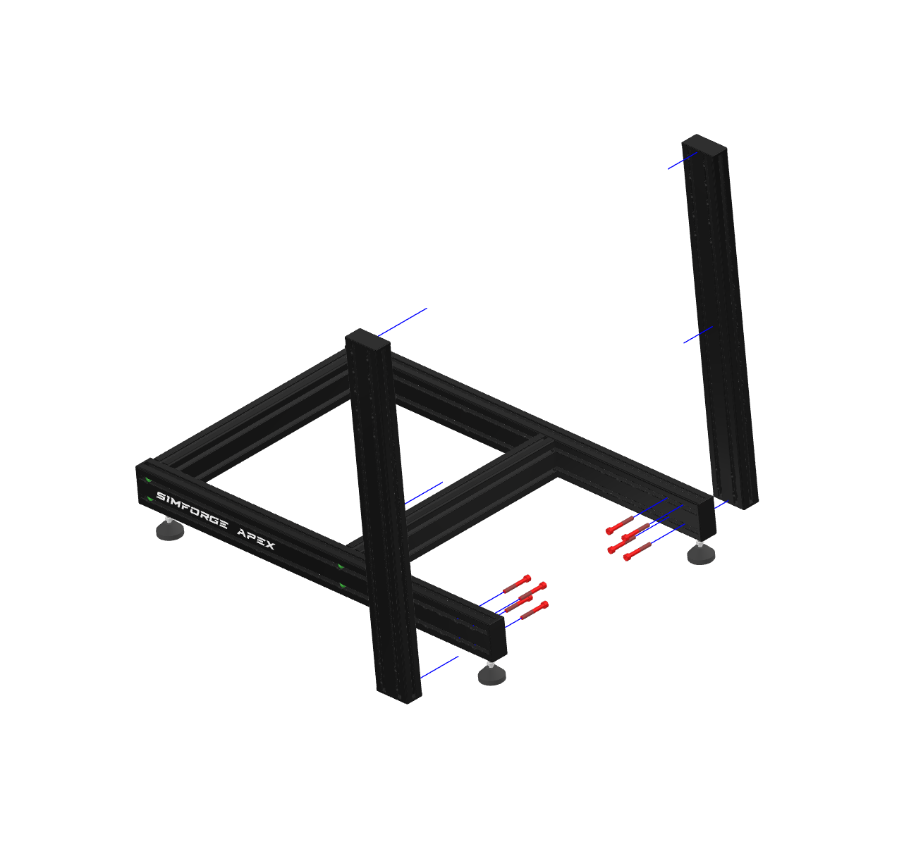
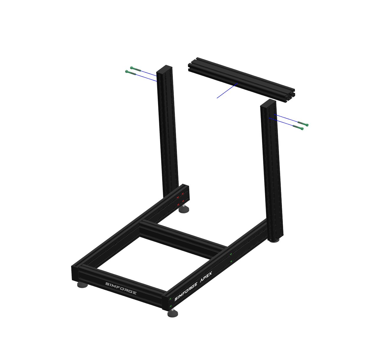
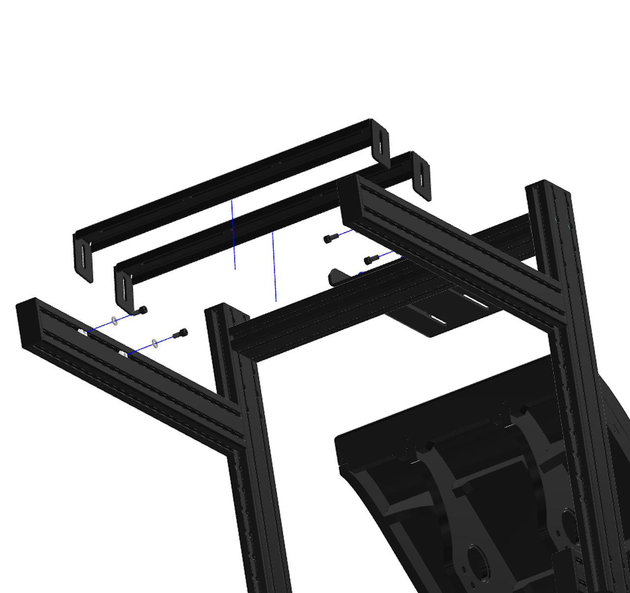
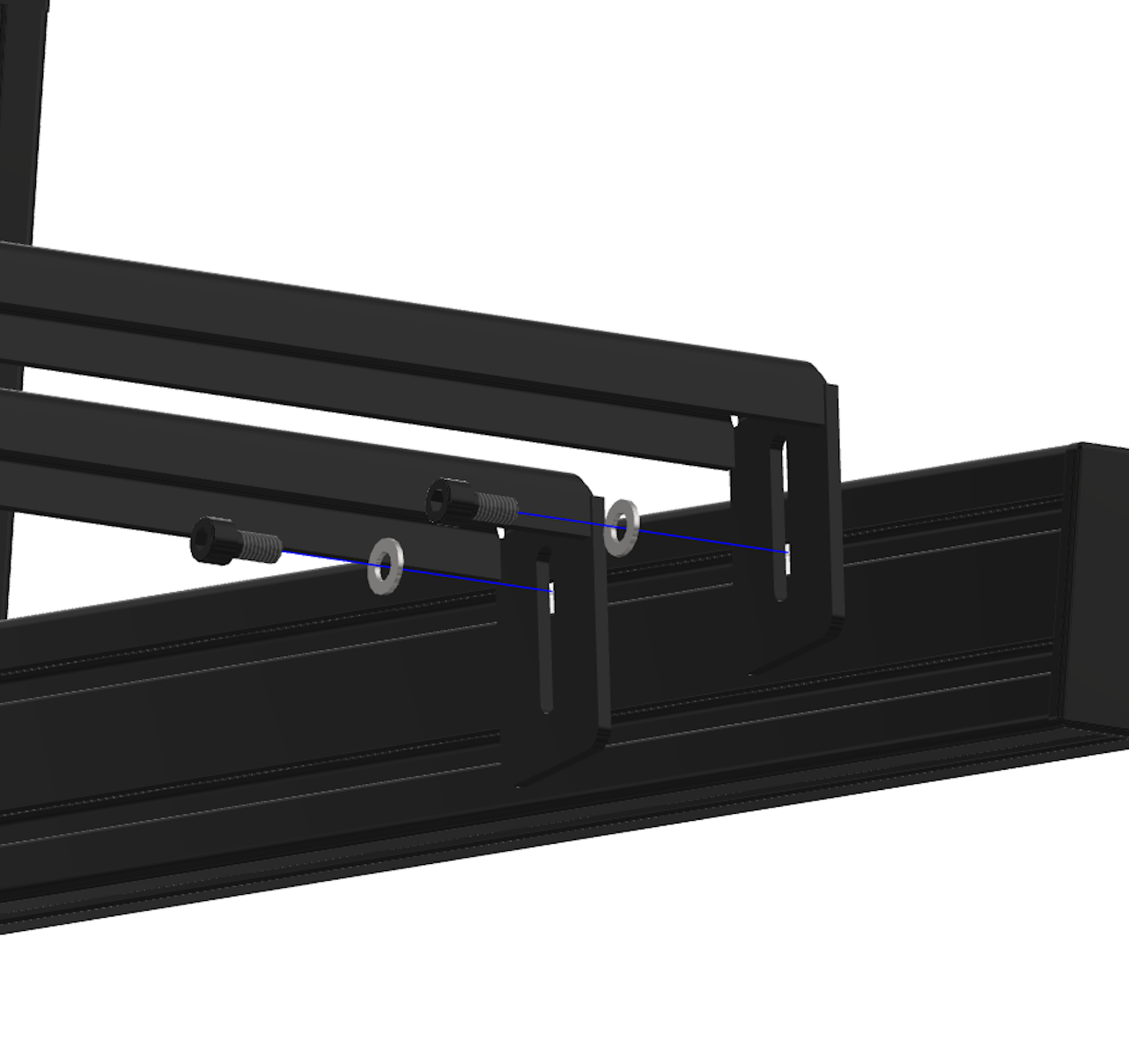
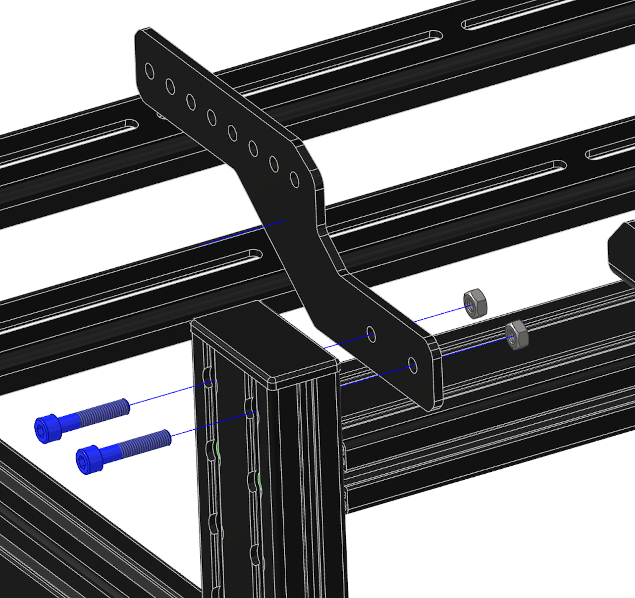
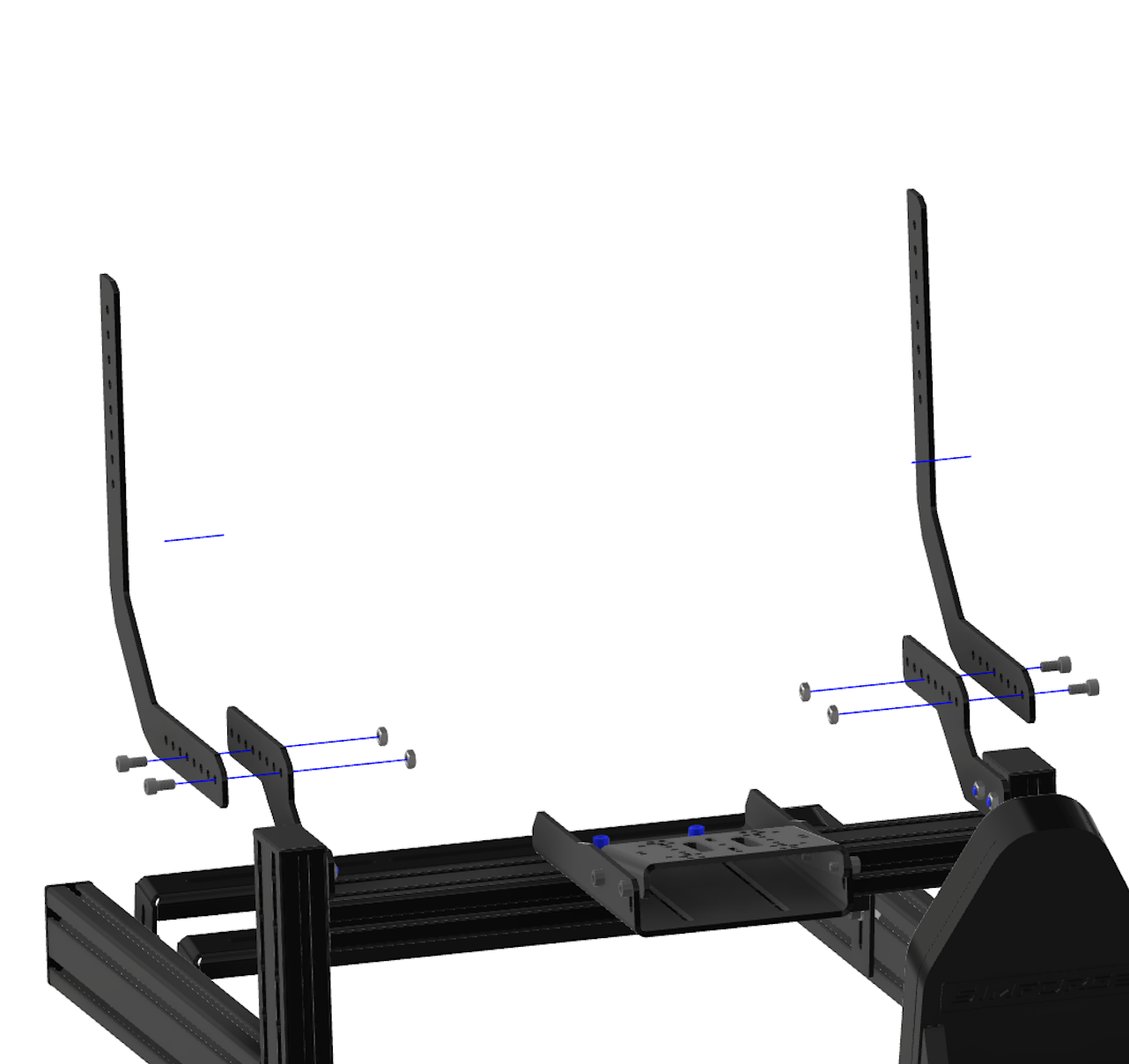
Cockpit Assembly Step 2

Parts used in Step 2 β€” wheelbase side profiles
Parts Used in this STEP
Sr No Parts QTY
1Wheelbase Side Profile [{|}]2
2Bolt – M8 Γ— 55 8
Step 2 – Install wheelbase side profiles on Simforge Apex rig

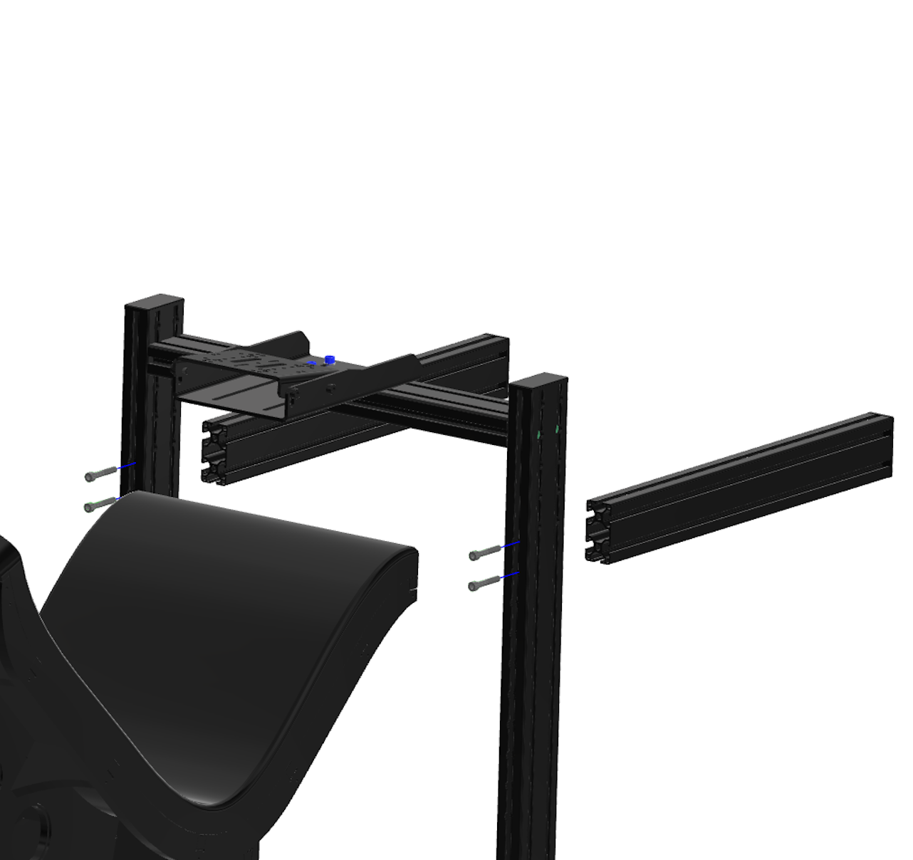
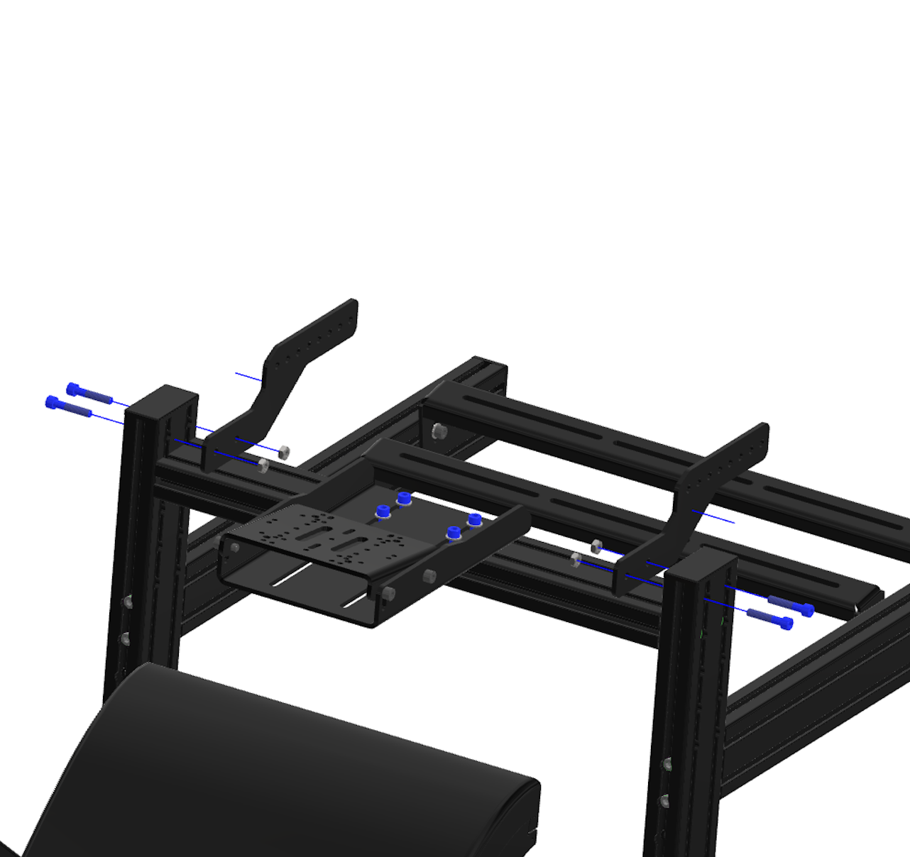
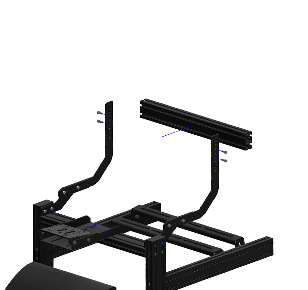
Cockpit Assembly Step 3

Parts used in Step 3 β€” middle profile for wheelbase support
Parts Used in this STEP
Sr No Parts QTY
1Wheelbase Middle Profile / Monitor Mount Middle Profile [{|}]
2Bolt – M8 Γ— 50 4
Step 3 – Mount middle profile for Simforge Apex wheelbase support

Cockpit Assembly Step 4 (Universal Wheelbase Mounting)

Parts used in Step 4 β€” universal wheelbase mount base
Parts Used in this STEP
Sr No Parts QTY
1Universal Wheelbase Mount Base
2Bolt – M8 Γ— 40 4
3M8 Washer4
Step 4 – Attach wheelbase base plate to Apex cockpit frame

Cockpit Assembly – Step 5 (Universal Wheelbase Mounting)

  • πŸ‘‰ Before starting this step, securely hard-mount your wheelbase to the Universal Wheelbase Mount.
  • πŸ‘‰ Extra bolts for hard-mounting the wheelbase are provided.
Parts used in Step 5 β€” universal wheelbase mount plate
Parts Used in this STEP
Sr No Parts QTY
1Universal Wheelbase Mount
2Bolt – M8 Γ— 16 4
Step 5 – Secure universal wheelbase mount for direct-drive wheelbases

Cockpit Assembly Step 6 (Simforge Apex Seat Mounting)

Parts used in Step 6 β€” Simforge Apex Seat mounting
Parts Used in this STEP
Sr NoPartsQTY
1Seat1
2Bolt – M8 Γ— 50 4
3M8 Washer4
  • πŸ‘‰ Tighten the seat bolts evenly and re-check after first use.
Step 6 – Install Simforge Apex racing seat on cockpit frame

Cockpit Assembly Step 7

  • πŸ‘‰ Choose the correct bolt holes to set your desired pedal height.
  • πŸ‘‰ The profile nuts for the pedal mounting plates (next step) are pre-installed. Ensure they face inward before attaching this profile.
Parts used in Step 7 β€” pedal side profiles
Parts Used in this STEP
Sr No Parts QTY
1Pedal Side Profiles [{|}]
2Bolt – M8 Γ— 90 4
Step 7 – Mount pedal tray and adjust pedal height on Simforge Apex cockpit

Cockpit Assembly Step 8

  • πŸ‘‰ Use this step to fine-tune the pedal height.
  • πŸ‘‰ Adjust the pedal angle as required in this step.
  • πŸ‘‰ Extra bolts and nuts are included for installing the pedals.
Parts used in Step 8 β€” pedal mounting plates and hardware
Parts Used in this STEP
Sr No Parts QTY
1Pedal Mounting Plates [{|}]
2Bolt – M8 Γ— 16
3M8 Washer
Step 8 – Assemble pedal mounting profiles with M8 bolts Step 8b – Adjust pedal angle for load-cell or hydraulic pedal compatibility

Step 9 Integrated Monitor Mount Installation

Parts used in Step 9 β€” integrated monitor mount (front plates)
Parts Used in this STEP
Sr No Parts QTY
1Front  Mounting Plates [{|}]
2Bolt – M8 Γ— 40 4
3M8 Hex Nut
Step 9 – Install front mounting plates for integrated monitor stand Step 9b – Attach rear mounting brackets for single monitor setup

Step 10 Integrated Monitor Mount Installation

Parts used in Step 10 β€” integrated monitor mount (rear plates)
Parts Used in this STEP
Sr No Parts QTY
1Back  Mounting Plates [{|}]
2Bolt – M8 Γ— 16 4
3M8 Hex Nut
Step 10 – Secure back mounting plates for monitor stand assembly

Step 11 Integrated Monitor Mount Installation

Parts used in Step 11 β€” monitor height fine-tuning hardware
Parts Used in this STEP
Sr No Parts QTY
1Back  Mounting Plates [{|}]
2Bolt – M8 Γ— 16 4
3M8 Hex Nut
  • πŸ‘‰ Use this step to coarse-tune the monitor height.
Step 11 – Fine-tune monitor height and alignment on Apex cockpit

Adjustable VESA Kit Adaptor Installation

Parts used in Step 12 β€” adjustable VESA kit adaptor and tools
Parts Used in this STEP
Sr NoParts / ToolsQTY
1Simforge VESA Adaptor Kit2
2Bolt – M4 Γ— 25 (Included with the Kit)4
3Taparia 974 Two in One Stubby Screw Driver (Included with the Kit)1
  • πŸ‘‰ Use the included spanner to tighten the screws for the monitor.
  • πŸ‘‰ Install the plastic spacers between the monitor and the VESA kit’s mounting plate.
Step 12 – Attach adjustable VESA kit adaptor to monitor stand Step 12b – Tighten screws and spacers for VESA adaptor installation

Installing the Simforge Vesa Adaptor Kit and monitor to the cockpit

  • πŸ‘‰ The Simforge Vesa Adaptor Kit can simply be placed on the profile.
  • πŸ‘‰ Adjust the angle of the monitor using the knobs for perfect FOV and alignement
Step 13 – Mount monitor to Simforge Apex cockpit using VESA adaptor kit

Upcoming Add-ons for Apex Sim Racing Cockpit

The Simforge Apex Sim Racing Cockpit and Simforge Apex Sim Racing Seat are designed not only for professional sim racing drivers but also for flight simulation enthusiasts. Upcoming add-ons will introduce full support for leading flight control systems including the Honeycomb Aeronautical Bravo Throttle Quadrant, Thrustmaster TCA Airbus Throttle Quadrant, Thrustmaster TCA Airbus Sidestick, Thrustmaster Boeing Yoke, and the VKB STECS Throttle System MK II. Engineered with precision-cut steel and aluminum profiles, the Apex cockpit delivers unmatched rigidity and modularity for both sim racing and flight simulation setups.

The next wave of Simforge add-ons will expand compatibility even further β€” introducing dedicated shifter and handbrake mounts, keyboard and mouse stands, PC and console shelves, and fully integrated triple and quad monitor mounts designed for high-end racing and flight simulator displays. These accessories will provide enhanced ergonomics, modularity, and immersion for every Apex cockpit owner.

All upcoming Simforge flight and racing accessories will be fully compatible with Microsoft Flight Simulator 2020 / 2024, X-Plane 12, and DCS World, ensuring seamless integration across the most popular sim racing and flight simulation platforms.

Contact

Sales & order changes: pitstop@simforge.in
Support & returns (RMA): boxbox@simforge.in Β· Support Center
Address: Simforge Engineering, Plot No-44, GAT No-661, Kolwadi, Pune-412110, India